Drum brakes - leading and lagging edge

AliK

Vehicle Dating Officer
Staff member
Club Member
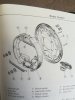
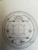
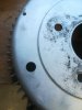
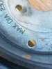
I’ve read about leading and lagging edge of brake shoes on drum brakes especially as mine were installed incorrectly by the PO as advised by a mechanic.

I think I have this the right way around - would someone kindly confirm for me or tell me otherwise?

b412a7690012b92a88cb47944a68f369.jpg
 

Farmer42

Club Member
Looks right to me Ali. That is also how the diagram looks in the Haynes manuals although someone will now probably tell me that the manual is wrong.
 

AliK

Vehicle Dating Officer
Staff member
Club Member
Thanks Mr Farmer! The trouble with the Haynes manual was that I couldn’t tell which side it was.

As I understand it, the bit with the least brake pad material should have the drum spin into it (if that makes sense).
 

toopy

Club Member
Thanks Mr Farmer! The trouble with the Haynes manual was that I couldn’t tell which side it was.

As I understand it, the bit with the least brake pad material should have the drum spin into it (if that makes sense).

That is my understanding also, something to do with the way the spinning drum grabs the front of the shoe forcing it downwards putting more pressure on the trailing edge of the shoe and so increasing the braking effect.
 
Last edited:

AliK

Vehicle Dating Officer
Staff member
Club Member
Ali,
It's worth 5 mins with a file to chamfer the leading edges as well.

Good advice sir!!! I saw that on the set I took off and wondered how it could possibly have worn that way! [emoji106]


That is my understanding also, something to do with the way the spinning drum grabs the front of the shoe forcing it downwards putting more pressure on the trailing edge of the shoe and so increasing the braking effect.

Yes that’s what I read too - trying to visualise it though is a little harder ;)
 

moggy240

Insurance Valuations Officer
Staff member
Club Member
From the nissan manual. Looks like you have it correct. I think I might need to check mine now.
 

Attachments

  • IMG_20200416_120033.jpg
    IMG_20200416_120033.jpg
    148 KB · Views: 24
  • IMG_20200416_120057.jpg
    IMG_20200416_120057.jpg
    123.3 KB · Views: 22

AliK

Vehicle Dating Officer
Staff member
Club Member
Thanks Moggy! The first diagram was the one I was looking at in Haynes but I couldn’t figure out which side it was ;)

Looking at it again I can see with the position of the handbrake mechanism that it is the same side that I was doing.
 

jonbills

Membership Secretary
Site Administrator
Are you sure you could even put them on the wrong way Ali? I think the location of the hole for the handbrake lever makes it pretty hard to put them on wrong.
 

AliK

Vehicle Dating Officer
Staff member
Club Member
Are you sure you could even put them on the wrong way Ali? I think the location of the hole for the handbrake lever makes it pretty hard to put them on wrong.

Yes sir, Put a line vertically in the middle and flip the image 180 and you’re there - quite easy to do.

There are two variations on the brake shoes. The ones that fit mine are uni-sex so to speak so you can fit them on either side.

2137e94faaae87c8052b667713e0d03b.jpg
 
Last edited:

jonbills

Membership Secretary
Site Administrator
Yes sir, Put a line vertically in the middle and flip the image 180 and you’re there - quite easy to do.

There are two variations on the brake shoes. The ones that fit mine are uni-sex so to speak so you can fit them on either side.

2137e94faaae87c8052b667713e0d03b.jpg
so you could put the one not attached to the handbrake lever in either way up?
hmm, I might have to look as well. [emoji4]
 

AliK

Vehicle Dating Officer
Staff member
Club Member
so you could put the one not attached to the handbrake lever in either way up?
hmm, I might have to look as well. [emoji4]

I think yours being an early 260 may have the other shoes that may not be uni-sex. Would be interesting to see - take a photo and show us yours! ;)

I think they look like this ...

b65de057cb7ad140e4ae9a4ce02d2ac9.jpg
 

moggy240

Insurance Valuations Officer
Staff member
Club Member
I had to adjust my rear cylinders and I did enlarged the adjusting hole as I had it before where you just can't see anything of the adjuster and it's a nightmare to slacken the shoes off to remove the drums. Just used a step drill from the back of the drum to open it up to 14mm with a 16mm step so I could fit a rubber grommet.
 

Attachments

  • IMG_20200420_120612.jpg
    IMG_20200420_120612.jpg
    141 KB · Views: 14
  • IMG_20200420_120556.jpg
    IMG_20200420_120556.jpg
    122 KB · Views: 13

Paul_S

Club Member
I had to adjust my rear cylinders and I did enlarged the adjusting hole as I had it before where you just can't see anything of the adjuster and it's a nightmare to slacken the shoes off to remove the drums. Just used a step drill from the back of the drum to open it up to 14mm with a 16mm step so I could fit a rubber grommet.
I like that mod! I think I might copy that the next time I have the rear jacked up :)
 

Rob Gaskin

Treasurer
Staff member
Site Administrator
I had to adjust my rear cylinders and I did enlarged the adjusting hole as I had it before where you just can't see anything of the adjuster and it's a nightmare to slacken the shoes off to remove the drums. Just used a step drill from the back of the drum to open it up to 14mm with a 16mm step so I could fit a rubber grommet.

I hope your re-balanced it.;)
 
Top