260z Restoration - Let's get started

Turn & Burn

Club Member
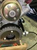
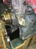
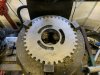
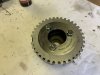
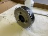
Just had a satisfying afternoon in the garage machining up a trigger wheel for the crank. I’ve gone with a kameari damper and surprisingly you can’t get an off the shelf trigger wheel. I thought being stainless it would be a bitch to machine but in the end pretty easy, sometimes stainless can work harden as u cut it and kills your tooling.
 

Attachments

  • 5136525F-6401-4365-8A77-A4FC789B89E9.jpeg
    5136525F-6401-4365-8A77-A4FC789B89E9.jpeg
    126.2 KB · Views: 42
  • 238E60C9-6294-40BD-A9CC-F221315941CA.jpeg
    238E60C9-6294-40BD-A9CC-F221315941CA.jpeg
    96.4 KB · Views: 42
  • C23741E6-8A5E-4B80-A6B0-05E6A21A0020.jpeg
    C23741E6-8A5E-4B80-A6B0-05E6A21A0020.jpeg
    84 KB · Views: 42

jonbills

Membership Secretary
Site Administrator
I put my trigger wheel behind the damper - lots of room back there.
67ae578916774cb70f5926aebe4a7f65.jpg

what fan arrangement do you have? I found the damper just fouled the stock viscous fan so I had to cut 2mm of the back of the fan blades.
 

Turn & Burn

Club Member
I put my trigger wheel behind the damper - lots of room back there.
67ae578916774cb70f5926aebe4a7f65.jpg

what fan arrangement do you have? I found the damper just fouled the stock viscous fan so I had to cut 2mm of the back of the fan blades.
That’s a really great idea, I didn’t think to get the damper off the hub. It may still be movable, but I’ll have opened the centerbore a bit much on the trigger wheel. I should have asked on here before I cracked on.
I’ll be using an electric fan so should be ok for room
 

jonbills

Membership Secretary
Site Administrator
I didn't take anything apart on the damper, just welded the trigger wheel on the back of it.
I say "I", but of course it wasn't me that did it. it was someone with a lathe and can weld straight :)
 

tyroguru

Club Member
Great work Andy! I too have a Kameari damper (this was in my plan before I decided to take it to bare metal...). I got a trigger wheel from http://trigger-wheels.com which obviously needs machining to fit and I was going to copy Jon and have it welded to the back of the damper. I took it to a machine shop to ask about it and he favored unbolting the damper and fixing it to the front as you have done here. Possibly stupid question: are the bolts there for fixing a plate to or are they fixing other pieces in the damper together? At the time I wasn't sure if the bolts could just be removed.
 

Turn & Burn

Club Member
Thanks Jon, i had the same thoughts as you about fixings, whether to weld etc. In the end I tried the bolts which took a big wrench to remove. Release torque was about 90nm so they’re 12.9 grade bolts. These can be replaced with cap heads m10x1.25p x 40mm to account for the thicker plate. The bolts hold the fluid ring onto the steel hub, but it also seems to be a press fit. I’m reluctant to try too hard to split it tho.
 

johnymd

Club Member
When I did my first trigger wheel I machined the standard damper and trigger wheel to fit together on the front of the damper and used 3 cap heads to fix it. I found the pickup stuck out a bit too far and had a bit of vibration which messed up the waveform a little. So this time I've fitted it the the back of the damper so the pickup is much closer to the engine and hoping for less vibration.
 

Turn & Burn

Club Member
When I did my first trigger wheel I machined the standard damper and trigger wheel to fit together on the front of the damper and used 3 cap heads to fix it. I found the pickup stuck out a bit too far and had a bit of vibration which messed up the waveform a little. So this time I've fitted it the the back of the damper so the pickup is much closer to the engine and hoping for less vibration.
It’s one of my concerns that it’s a bit far forward, but it’s the suggested fixing for the ATI dampers I’ve copied. It shouldn’t pick up vibration if it’s in balance tho? I maybe need to add a balance hole opposite the removed tooth.
 

Bazzateer

Club Member
It’s one of my concerns that it’s a bit far forward, but it’s the suggested fixing for the ATI dampers I’ve copied. It shouldn’t pick up vibration if it’s in balance tho? I maybe need to add a balance hole opposite the removed tooth.
If I'm reading him correctly I think John means the sensor/pickup had some vibration, not the wheel?
 

moggy240

Insurance Valuations Officer
Staff member
Club Member
I would have thought the crank position sensor would be better mounted the other side away from the alternator. IMG_20200704_132950.jpg
 

Turn & Burn

Club Member
I would have thought the crank position sensor would be better mounted the other side away from the alternator. View attachment 39822

I’m not the 1st person to place it here, but I’ll ask around. Would have gone with a similar location to yours but I’m running a larger damper pulley and it starts to look like a bit of an ugly fabrication


Sent from my iPhone using Tapatalk
 

moggy240

Insurance Valuations Officer
Staff member
Club Member
Mine was picking up electrical interference from my electric water pump, away from electrical source if possible is a good idea.
I did get it sorted in the end and had some resistors fitted online as the electric water pjmp was messing up the crank position sensor signal.
 
Last edited:

Turn & Burn

Club Member
Mine was picking up electrical interference from my electric water pump away from electrical source if possible is a good idea.
I did get it sorted in the end and had some resistors fitted online as the electric water pjmp was messing up the crank position sensor signal.
I’ve taken ur advice, it’s an easy enough job with the engine out, so why risk issues later on. Thanks...
 

Attachments

  • 5EE02314-C6C5-43E0-BF5A-B7AF489E304D.jpeg
    5EE02314-C6C5-43E0-BF5A-B7AF489E304D.jpeg
    224.6 KB · Views: 41
  • F60941B1-118D-4811-88F4-B852FC41213A.jpeg
    F60941B1-118D-4811-88F4-B852FC41213A.jpeg
    200.4 KB · Views: 40

Turn & Burn

Club Member
Installed the motor on Sunday evening, straightforward stuff apart from oil pouring out of the gearbox flange. I had the great idea of filling the box beforehand cos i thought access maybe tricky later on. Turns out it was a rubbish idea, I sealed the output shaft but never considered it would come out the gearlever flange instead. As it is it’s dead easy to get at the fill plug so I needn’t have bothered.
Newly manufactured gearbox cradle lines up well enough give or take a few mm so happy days.
 

Attachments

  • 66288523-8512-41E8-8C80-324EDD8917C7.jpeg
    66288523-8512-41E8-8C80-324EDD8917C7.jpeg
    387.6 KB · Views: 45
  • C733BD2A-EE68-4E54-B714-12C366ABF79D.jpeg
    C733BD2A-EE68-4E54-B714-12C366ABF79D.jpeg
    264.5 KB · Views: 46
  • FCAD29A9-CD0D-423A-8637-0BF9CB32DFA9.jpeg
    FCAD29A9-CD0D-423A-8637-0BF9CB32DFA9.jpeg
    348.2 KB · Views: 45
  • E36D518D-7473-4DD3-AFD5-E6D2F10D2BA7.jpeg
    E36D518D-7473-4DD3-AFD5-E6D2F10D2BA7.jpeg
    224.3 KB · Views: 47
  • D92F945D-5A98-4F9A-B6C9-8ABABB7A66EB.jpeg
    D92F945D-5A98-4F9A-B6C9-8ABABB7A66EB.jpeg
    366.6 KB · Views: 48

Turn & Burn

Club Member
My exhaust is running very close to the footwell corner where it passes into the tunnel, almost a rub, and I’m considering shaving the manifold flange on a very slight angle, even a 0.5mm angled cut on the face will give me 10mm increase at the tight spot. Other options are a bit of persuasion on the pipes but this often ends badly with stainless and it cracks later.
 

jonbills

Membership Secretary
Site Administrator
My exhaust is running very close to the footwell corner where it passes into the tunnel, almost a rub, and I’m considering shaving the manifold flange on a very slight angle, even a 0.5mm angled cut on the face will give me 10mm increase at the tight spot. Other options are a bit of persuasion on the pipes but this often ends badly with stainless and it cracks later.
thats a good idea. mine proper hit the passenger footwell and ended up bashing the footwell, which I regret now.
 
Top