BACKGROUND
I lie in bed at night thinking of this stuff but then comes a moment of madness when I decide to do something about it, so here goes. (Having said that, this could end up being a very long experiment happening in glacial timescales as it will be an as and when effort - so please bear with me).
David Vizard - a brilliant brilliant engineer whose automotive work and thinking I greatly admire - showed that with simple modifications to the SU carb, they can flow as much as the next size up, but without “over-carbing” the engine.
I could just fit 2” SUs - but where’s the fun in that!? Besides, I want to see just how much could be extracted from the Hitachis. So the purpose of this thread is to document my modifications on the Hitachi 44.5mm SU carbs and indulging my curiosity! Especially as I can't find anyone who's done them to their SUs in the Z world and laid out what they did.
In summary, looking at Mr V’s article (attached), he shows the following impressive gains from these mods.

ChatGPT tells me that 240z Hitachis were rated at 180-200CFM - but it steadfastly refuses to divulge it's reference! For comparison, HS6s have a measured max flow rate of 210CFM, so I used the mid CFM of the Hitachi for my theoretical column in grey. For a bit of fun I unscientifically derived the potential CFM improvements using the % improvement of the HS4 in the article. (Incidentally, no.7 is omitted as it was without the butterfly).

The big ticket items are obvious but what surprised me the most was the effect of cutting away the protruding screws! I suspect that's got more to do with fluid dynamics and turbulence than their cross sectional area. The other item that surprised me was how much flow was gained by rounding off the burrs and sharp edges in the piston area. We often read about turbulence reducing the effective flow but wow over 6%!
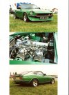
For anyone wondering what those mods can look like (except for the low res. photos in the article), here are some pics I stole of 'tinter.
Piston - looking at our carbs the piston really doesn't have a material protrusion, but this picture is extreme and interesting all the same.

Shaft mods

Bores - Smoothing off the bores where the casting has lots of burrs - it's important to not take this one too far otherwise the piston can't do it's job as well.

THE PLAN
So what we are aiming for are low hanging fruits and some slightly more involved work. What I plan is:
I will leave the bridge well alone as I’ve read people have destroyed their carbs modifying this bit. There are all kinds of flow mechanics involved in creating vacuum across the jet / nozzle and required turbulence for fuel atomisation / accelerator pump function.
SOME MATHS ON THE HITACHIS
Carb opening = 44.5mm
Shaft diameter =10mm
Butterfly height=2mm
Bridge height = 7mm
Butterfly bolts= M4 and sticking out by 4mm
For simplicity let’s ignore the butterfly screws and their presented cross section.
- Shaft and butterfly cross sectional area presented at WOT = 10 x 44.5 = 445mmsq
- Carb barrel cross sectional area: 44.5/2 squared x Pi =1555.5 mmsq
So in effect the shaft and butterfly constitute 445/1555.5 = 29% of the carb barrel!!
- Bridge area = 141.3sqmm (if you really want to know how to calculate that, see https://planetcalc.com/1421/)")
- But if you deduct the bridge cross section to arrive at the actual available cross-sectional area through the carb =1555.5-141.3 =1414.13mmsq
- So the shaft and butterfly as a percentage = 445 / 1414 = 31% of the opening when looking through the carb!!
That is an ASTONISHING amount. No wonder Mr Vizard’s mods, however small they may seem, have a significant impact. And that’s before you take fluid dynamics and flow reducing turbulence effects into account!!
To satisfy myself, I made a to scale drawing:

So the numbers and theory seem promising on paper!
Next up, the guinea pig spare carbs and possible home made way of measuring improvements in flow - tune in again next time, same time, same channel.
I lie in bed at night thinking of this stuff but then comes a moment of madness when I decide to do something about it, so here goes. (Having said that, this could end up being a very long experiment happening in glacial timescales as it will be an as and when effort - so please bear with me).
David Vizard - a brilliant brilliant engineer whose automotive work and thinking I greatly admire - showed that with simple modifications to the SU carb, they can flow as much as the next size up, but without “over-carbing” the engine.
I could just fit 2” SUs - but where’s the fun in that!? Besides, I want to see just how much could be extracted from the Hitachis. So the purpose of this thread is to document my modifications on the Hitachi 44.5mm SU carbs and indulging my curiosity! Especially as I can't find anyone who's done them to their SUs in the Z world and laid out what they did.
In summary, looking at Mr V’s article (attached), he shows the following impressive gains from these mods.
ChatGPT tells me that 240z Hitachis were rated at 180-200CFM - but it steadfastly refuses to divulge it's reference! For comparison, HS6s have a measured max flow rate of 210CFM, so I used the mid CFM of the Hitachi for my theoretical column in grey. For a bit of fun I unscientifically derived the potential CFM improvements using the % improvement of the HS4 in the article. (Incidentally, no.7 is omitted as it was without the butterfly).
The big ticket items are obvious but what surprised me the most was the effect of cutting away the protruding screws! I suspect that's got more to do with fluid dynamics and turbulence than their cross sectional area. The other item that surprised me was how much flow was gained by rounding off the burrs and sharp edges in the piston area. We often read about turbulence reducing the effective flow but wow over 6%!
For anyone wondering what those mods can look like (except for the low res. photos in the article), here are some pics I stole of 'tinter.
Piston - looking at our carbs the piston really doesn't have a material protrusion, but this picture is extreme and interesting all the same.
Shaft mods
Bores - Smoothing off the bores where the casting has lots of burrs - it's important to not take this one too far otherwise the piston can't do it's job as well.
THE PLAN
So what we are aiming for are low hanging fruits and some slightly more involved work. What I plan is:
- De-burring the walls of the carb to minimise the effects of flow reducing turbulence
- Reducing the effect of the butterfly screws
- Reducing the effect of the shaft
- Edging the butterfly
- And a VERY bad idea I have which will involve some CNC accurate work, which I’ll divulge later...
I will leave the bridge well alone as I’ve read people have destroyed their carbs modifying this bit. There are all kinds of flow mechanics involved in creating vacuum across the jet / nozzle and required turbulence for fuel atomisation / accelerator pump function.
SOME MATHS ON THE HITACHIS
Carb opening = 44.5mm
Shaft diameter =10mm
Butterfly height=2mm
Bridge height = 7mm
Butterfly bolts= M4 and sticking out by 4mm
For simplicity let’s ignore the butterfly screws and their presented cross section.
- Shaft and butterfly cross sectional area presented at WOT = 10 x 44.5 = 445mmsq
- Carb barrel cross sectional area: 44.5/2 squared x Pi =1555.5 mmsq
So in effect the shaft and butterfly constitute 445/1555.5 = 29% of the carb barrel!!
- Bridge area = 141.3sqmm (if you really want to know how to calculate that, see https://planetcalc.com/1421/)
- But if you deduct the bridge cross section to arrive at the actual available cross-sectional area through the carb =1555.5-141.3 =1414.13mmsq
- So the shaft and butterfly as a percentage = 445 / 1414 = 31% of the opening when looking through the carb!!
That is an ASTONISHING amount. No wonder Mr Vizard’s mods, however small they may seem, have a significant impact. And that’s before you take fluid dynamics and flow reducing turbulence effects into account!!
To satisfy myself, I made a to scale drawing:
So the numbers and theory seem promising on paper!
Next up, the guinea pig spare carbs and possible home made way of measuring improvements in flow - tune in again next time, same time, same channel.
Attachments


Last edited: