I've been staring at circuit diagrams for the last two hours, but none of them are specific to my car. This is what I've worked out so far:
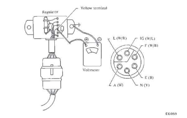
Pin 1:
L - White/Red - Missing wire, it should apparently go to the charge lamp in the dash then on to +12v ignition @ fuse box
Pin 2:
A - White - Alternator output to battery
Pin 3:
N - Yellow - Sense wire (connects to 'N' on alternator)
Pin 4:
E - Black - Ground
Pin 5:
F - White/Black - Lamp connection (connects to 'F' on alternator)
Pin 6:
IG - White/Blue - True +12v ignition source (whatever 'true' means)
To bypass the Voltage Regulator:
Pin 1 connects to Pin 5 (with a diode in-between)
Pin 2 connects to Pin 3
Seeing as I have an ammeter instead of a voltmeter I don't have a charge lamp. Is that why I don't have a white/red wire in the harness? If so, then what do I connect the cathode of the diode to?
[EDIT] Thinking about it, the diode would need to be connected to a switchable +12v source, which I assume would be pin 6. Is that right? I don't want to fry anything!
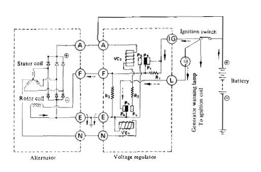
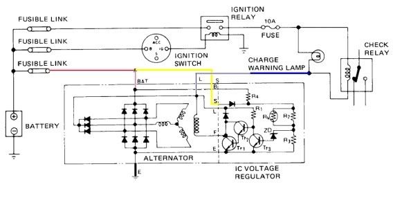
[EDIT 2] Looking at the circuit diagrams for internally regulated and externally regulated alternators, the main difference is that everything goes through the
L connector on the internally regulated version negating the need for an
IG terminal. So comparing the two, it looks like I can just use the
IG wire on my harness to connect to the diode, in order to excite the alternator when the ignition is turned on. If someone with more brains than me could confirm that, then I'd be grateful.
Externally regulated:
Internally regulated: