L26 Restoration Build

So its time that I share with everyone on here what I and my close friend have been up to behind the closed doors of the garage.

The engine,
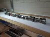
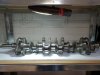
L26; the engine has been pulled from the car for the chassis to be restored has been sat for the last 30 years. It was indeed in a rough state and although I have done a few classic restorations for Escorts in my time I haven't come across one that has been stood for so long without running. The engine how ever was not missing any parts or showing any signs of outside damage; none of the bolts had been touched or rounded and everything looks like it should.

The plan,
Strip and rebuild to a OEM spec including some small improvement and refinement on the original spec without going over board and moving away from the factory design. In a few words making a clean example of how the L26 should have been from the factory.

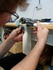
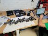
All data recorded for the strip and rebuild, with pictures and build sheets along the way. The plan for the build to be fully traceable and the owner to be able to look back on the build and see all measurements and data if he wishes so.

I hope to post once a week with pictures and updates and no doubt a bizillion questions.

I will try and start another thread for looking for replacement parts as to what spec and where to get them from which I hope other members will be able to help with.

Please at any point if anyone has any questions/hints - tips/advice/guidance/general banter by all means post up or drop me a message.

Now lets try and upload some initial pictures, bear with me its been a while since I used forums.....
 
Last edited:

Farmer42

Club Member
Did a similar L26 rebuild about 18 months ago & posted a thread on it with pics. I was lucky in that all the internals and cam were fine and used most of the ancillaries from my L20 engine that I was swapping out so that kept the costs down. Still cost me around a Grand plus the cost of the engine to start with. New oil & water pumps are a must but are not expensive & available. Also timing chain kit. If you don't already have one get an electronic dizzy to make the most of the power and help the rebuilt engine run smoother. Finally get the manual " How to rebuild your Nissan & Datsun ohc engine". Much better than a Haynes.

Good luck & enjoy. It's really satisfying when you fire it up for the first time.
 

Wally

Club Member
I'm using tapatalk and no pictures unfortunately. Just address lines.


Sent from my iPhone using Tapatalk
9c0562085568d642e1307ab66a14a6a2.png
 
Sorry for the delay on posting I will try and get more consistent as time goes on; we have all been very busy doing builds, car repairs, garage plaster boarding and tidying.

So…

The engine has now been stripped down to its individual components I’ll structure this post mainly looking at the head and valve train.


When stripping the engine an electronic torque wrench was used to measure “break away” torques to get an idea if anything was suspect or needed further investigation.

From the data gathered removing the cylinder head, main bearing caps and conrods, show that everything is how I would expect it to be; torque values all being even and within a sensible margin of each other.


Confident that everything is how it should be (and of course referring to the Datsun build book (with the guy with the healthy mustache) and online sources) the strip continued.


The distributor was inspected and in very good condition. The oil/water pump was the same.


The cam, lash pads, rocker arms and all valve train components show very little wear with no surface damage to either face. Except for the amount of “old” oil left in the cylinder head and around the engine from being sat for so long.


Throughout the strip no bolts on the engine looked as if they had been touched before with no spanner rash or damage with every bolt being removed with ease and complete lack of swearing! So far I’m growing fonder and fonder of this engine and how easy it is to work on it.


As you can see a valve board was made to keep everything in order so that all the parts go back as they came off.


The next step is to start cleaning everything ready for the masses of measuring which will take place.


I shall after the weekend start a thread on the classifieds discussion page as to where and what parts will need sourcing for the build.


Keep safe and until next time.

(Also again let me know if the images are viewable.. I swear I will get there with this one way or another!)


Cam Head Carriers.jpg Cam Lobe Wear.jpg Cam Sprocket.jpg Cylinder Head.jpg Dizzy.jpg Dizzy.jpg Head and Valve train.jpg Head Old Oil.jpg Rocker Arms.jpg Water Pump.jpg
 
Last edited:

jonbills

Membership Secretary
Site Administrator
Yep, those pics show, even on Tapatalk [emoji106]
Looks just like my L28 did.
 

Farmer42

Club Member
That water pump may look ok but you don't know how old the seals are. As was pointed out to me, the last thing you want is to spend all that money on refurbishing your engine and an old water pump lets go and wrecks it when it overheats. For the price of a new one (about £25) ditch it and buy a new one. Same with the oil pump and pressure sender. They are all easily available from Mr F or other means. For me it just wasn't worth the risk.

Otherwise, it all looks in good condition. Are you really going to keep a mechanical dizzy? It will run so much better on an electronic.

Finally, I found the thread & write up from when I did mine.

https://zclub.net/community/index.php?threads/l26-engine.21335/
 

Geoff-R

Club Member
I'm in a similar situation, my engine hadn't run in easily over 30 years. Last time the car had an mot I don't think I was born! Stripped the engine down and it was in incredible condition internally, externally it looked shocking although, like you, nothing missing.
 
Good Afternoon all,

Franky, can you pm me some details of the pistons please as I would like to consider brand new for this build for sure.

Farmer42, I will take your advice and look into alternative pumps for both the water and the oil. And yes the engine will stay as it is and was intended from the factory so mechanical dizzy it is. As much as I am a believer of modern tech and have tried to convince the owner to update items, for this build it shall be 100% OEM. Hopefully the next one or one after we can look into doing some fancy pants bits.

Geoff-R, Geoff I like your choice of vehicles with the CSL and the 260z, beautiful cars. Haha yes its getting close to a lot of these parts where last used before I was even born and for sure they look in better nick than I do in some respects.. we all rust with age.


So the main post for this week,

With the arrival of the parts washer and some solvent the cleaning process can start on all the parts.

Without one of these tanks I can’t imagine how long it would take to clean everything to the same degree. I’ll let the pictures speak for themselves when it comes to learning stuff.

Firstly, a check of the head to see if it is in spec for flatness; before putting the straight edge onto the fire face some cleaning and removing of the old head gasket had to happen first.

Not wanting to change the dimensions of the surface just yet only a light sanding was done using a stone to keep the surface as flat as possible. With this done the straight edge was used with some feeler gauges in various directions to establish what shape the head was in. The tolerance from the moustache man said that a head limit was up to 0.100mm with a maximum variation of 0.050mm.

Checking this head in all directions showed that it was maximum of 0.080mm; now using the straight edge to polish the high spots on the head (crude way until I can source a nice granite surface table) showed that there needed to be some more flattening to the face to remove these spots (this will be done on a surface table so that it only removes the highest points and will being the face a lot more flat.

Before more work was to be done to the head the ports and combustion chamber are to be fettled. The idea being not to over size the ports in any way but to smooth and blend the shape, basically to remove any of the original casting marks and smooth the ports to aid the flow of air into the chamber. One of the things I have learnt from previous engine dyno testing is that smoothing the valve seat into the ports aids the flow and does increase power ever so slightly (in the higher rpm range) so this was the first thing that was done, then following onto smoothing or as some say a port and polish.

Now there’s various ideas bounced around regarding the finish on a port, where the intake should stay rough and an exhaust smooth and shiny and the levels of “polish” that goes into the ports.

Generally, it’s the shape of the ports that give the swirl/tumble/mix of the air and fuel depending of course where the fuel and how the fuel is injected.

So, for this head a mirror finish on either port is not needed but a smooth surface and shape will aid the flow and mix into the chamber.

For the combustion chamber again, general rule is that if there are any peaks or sharp edges these are areas of heat build up which then in turn leads to det being prone to occur in these areas so the threads protruding into the chamber where smoothed as well as the general shape. Again, not changing the shape or the size (until the cc’s are measured that is)

With the head work underway and something around 20hours so far accumulated on the head a break was needed so some measuring of some of the other components can start. Once the final cleaning has happened (which I am currently looking into acid dipping to clean out all of the galleries and passage ways on both the cylinder head and the block) the cylinder head will go through the fire face flattening and the ports finally finished.

The crank mains and pins where measured… I should say before we continue that the mic’s that where bought for the garage have all been calibrated; are cleaned and checked before all measuring starts; the temperature of the room is recorded and any adjustments made depending on the temperature at the time being rather cold and still working on the garage we have to make adjustments for it being so cold; ideally I would like the temperature to be at 20 degrees for all measuring for the materials to be stable and making sure all the parts are heat soaked to this temperature.

The crank when measured and the results were in the middle of the manufacturers tolerance being only a maximum of 0.006mm adrift between each other and up to 0.003mm out of round and cylindrical.

The lash pads where all mic’d as reference for further investigation (if anyone has information on the factory sizes or increments?)

The valves have been cleaned, and the stems and lengths measured to check for any necking – stretching.


The next stage is to look at the bearings; to measure the block’s main bearing journals, conrod bearings and record our findings and make suitable bearing selections. The tolerance on the bearings to me seems absolutely huge! So, the question to you guys is to what end of the tolerance do these engines prefer; the old trick of loose is fast works in most cases to a point of loss of adequate oil pressure or in terms of ring gaps - too much blow-by gases and too high a pressure in the crank case / loss of combustion pressure resulting in of course loss of power.


I shall try and find and post up some images of the ports I designed during my uni work so you can see how air flows in at least one example into a port around a valve. These images I have found just show air velocity through a port with two different radially changed profiles as an example; also showing how the air enters the chamber with the valve at max lift and how it interacts inside the chamber. If anyone has any questions fire them over.

Before_Intake.jpg Before_Intake_Exhaust.jpg
 

Attachments

  • Before_Throats.jpg
    Before_Throats.jpg
    174.1 KB · Views: 46
  • Camshaft_Clean.jpg
    Camshaft_Clean.jpg
    218.2 KB · Views: 45
  • Camshaft_Measure.jpg
    Camshaft_Measure.jpg
    122 KB · Views: 45
  • Crankshaft_Clean.jpg
    Crankshaft_Clean.jpg
    255.7 KB · Views: 47
  • Crankshaft_Measure.jpg
    Crankshaft_Measure.jpg
    295.4 KB · Views: 46
  • Half_way_intake.jpg
    Half_way_intake.jpg
    84.9 KB · Views: 45
  • Half_way_Intake_Exhaust.jpg
    Half_way_Intake_Exhaust.jpg
    127.6 KB · Views: 45
  • Half_way_Throats.jpg
    Half_way_Throats.jpg
    180.9 KB · Views: 46
And now I know you can only post 10 images at a time, I am sorry guys I will get on top of this posting thing eventually, you'd think for someone in his 30's this should be a doddle; hand me tools over computers is all I'll say. Here are the port images.

High_Floor.jpg Low_Floor.jpg Port_Flow.jpg

Also as a disclaimer ports seem to be rather hard to picture true to what they look like in real life, I shall try harder once they are finished to a standard I would call them done.
 
Just a quick update as not much has happened over Christmas unfortunately and other commitments have just got in the way left right and centre of the build.

The block and the head as well as the exhaust manifold have been dropped off to be chemically cleaned and hopefully back at the end of the week.
The decision to balance the whole rotating assembly has been made to help the motor run as smooth as possible and also the option to add some extra rpm if wanted (everyone wants more rpm I mean who doesn't right?)
The paint has been found for the block so once it comes back from being cleaned it shall be painted up to protect and then some more measuring can take place!

I have also been a little preoccupied by my triangle engine which has been in the process of being rebuilt also.

I am also in the process of making some little electrical gadgetry to help "tune" engines as a whole so a few images and information about them will be popping up over the next couple of weeks.

Hope this all finds you well and your out enjoying this weather whilst we have it!!
 
Rob - the triangle engine I refer to is the 13b for my rx7 I am but of course rebuilding...again, 413bhp at 7krpm 0.8bar of boost was its first build until it decided it didn't like oil being inside it anymore so this build I'm going for 10krpm, 1bar and well see what happens with the power figures after that.

haha uk66fastback - yeah little temp probe set ups, knock box, and I want to look into making a manifold for the z's with a lambda in each port. The idea on the temp probe is so that I can measure under bonnet temps in many places to see what air flow needs to be adjusted.

There should be more updates next week if I can get the block back this week, would like to get the bores measured and some pistons/rods/bearings ordered so that I can get the rotating assy off to be balanced.

Here's the Kameari piston pics you asked for.

9gyTD6v.jpg

AKbXV6e.jpg

V1b6gG4.jpg
 
Top